Domestic spread spectrum anti-interference low cost serial port 433M wireless communication module Lora remote UART AD hoc network
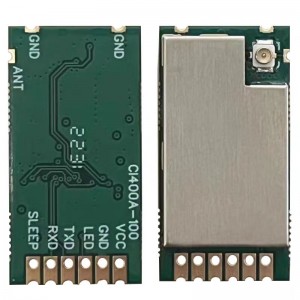
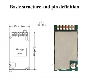
| Pin number | Pin name | Pin direction | Pin use |
| 1 | VCC | Power supply, must be between 3.0 and 5V | |
| 2 | GND | Common ground, connected to the power supply reference ground power | |
| 3 | LED | Output | Pull it down when sending and receiving data, and pull it up in normal times |
| 4 | TXD | Output | Module serial output |
| 5 | RXD | Input | Module serial input |
| 6 | SLEEP | Input | Module sleep pin, pull down the wake up module, pull up to enter sleep |
| 7 | ANT | ||
| 8 | GND | Common ground wire, mainly used for welding fixed modules | |
| 9 | GND | Common ground wire, mainly used for welding fixed modules |
Characteristic function
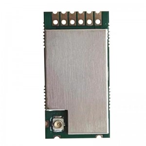
Based on the pure domestic low-power long-distance spread spectrum chip PAN3028, the communication distance is long and the anti-interference ability is strong; Pure and transparent transmission, fully adapt to different customer requirements; Remote wake-up to achieve ultra-low power consumption, suitable for battery-powered application scenarios; Support RSSI signal strength printing, used to evaluate signal quality, improve communication effect and other applications;
Supports deep hibernation. The power bit of the module in deep hibernation is 3UA. Support 3~6V power supply, more than 3.3V power supply can ensure the best performance; Dual antenna design with support for IPEX and stamp holes; The rate and spread spectrum factor can be arbitrarily configured according to the actual usage scenario. Under ideal conditions, the communication distance can reach 6 km; The power is adjustable in multiple stages.
Use tutorial
The CL400A-100 module is a pure transparent transmission module that automatically enters transparent transmission mode after power-on. If the corresponding parameters of the module need to be configured and modified, the corresponding AT command can be directly sent (see AT instruction set for details). The module supports three working modes, namely general transmission mode, continuous sleep mode, and periodic sleep mode.
1. General transmission mode:
Pull down the SLEEP pin, power-on automatically enters the general transmission mode, AT this time the module has been in the normal receiving state, can receive wireless signals or transmit wireless signals, in this mode can directly send the corresponding AT instruction, you can change the parameters of the module (change the parameters of the module can only be carried out in this mode, other modes can not be changed).
2, always sleep mode:
It is necessary to set the module parameter to AT+MODE=0 in the general transmission mode, and then control the SLEEP pin to pull up, and the module can enter the continuous sleep mode. At this time, the module consumes very low current, the module is in the deep sleep state, and no data will be sent or received. If the module needs to start working, the SLEEP pin needs to be pulled down.
3. Periodic sleep mode:
In the general transmission MODE, set the module parameter to AT+MODE=1, and then control the SLEEP pin to raise, and the module can enter the periodic sleep mode. At this time, the module is in the alternating state of hibernation standby – hibernation standby – hibernation. The maximum hibernation period is 6S, and it is recommended not to exceed 4S, otherwise the sending module will be seriously hot. And the sending module requires the PB value to be greater than the sleep period.
Products categories
-

Phone
-

E-mail
-

Whatsapp
-

Skype
-

Skype
-

Skype


