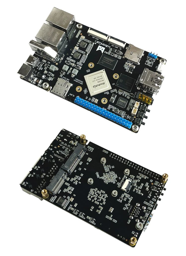
HC-05 HC-06 Bluetooth to Serial Adapter module Group CSR Master-Slave 51 MCU new original
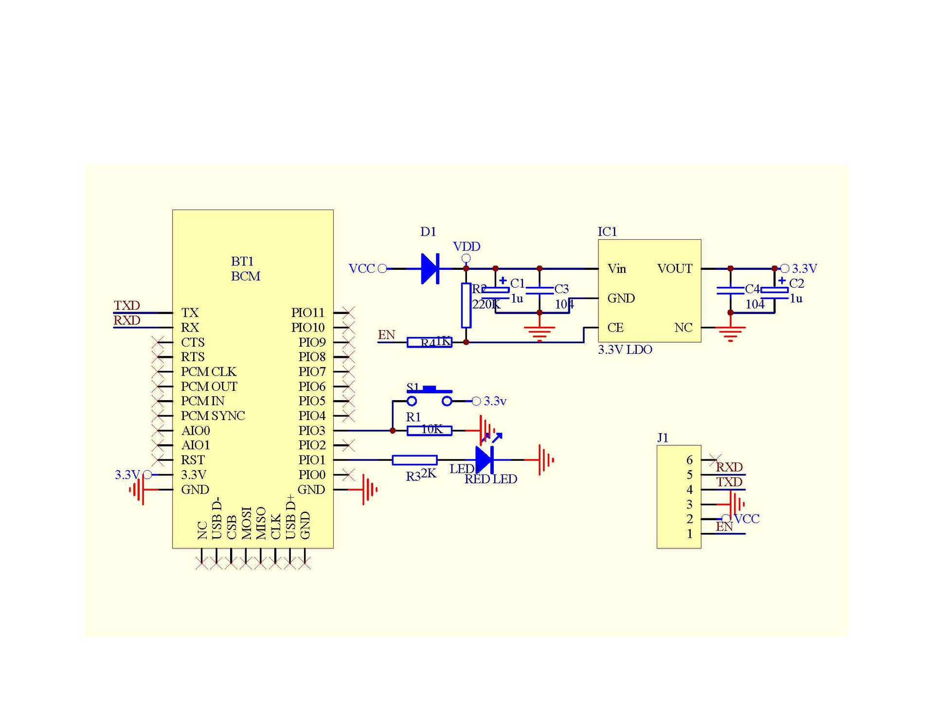
Pin definition used in serial module:
1. PIO8 is connected to the LED to indicate the working status of the module. After the module is powered on, the blinking interval is different for different states.
2. PIO9 connects to the LED, indicating that the module is connected successfully, and the LED will keep bright after the Bluetooth serial port is matched and connected successfully.
3, PIO11 module status switch foot, high level –>AT command response working status, low level or suspended –> Bluetooth routine work
Make a state.
4. There is a reset circuit on the module, and the reset is completed after re-powering.
Steps to set up the master module:
1, PIO11 set high.
2. Power on the module and enter the AT command response state.
3. Hyperterminal or other serial port tool, set baud rate 38400, data bit 8, stop bit 1, no check bit,
No flow control.
4, serial port to send the character “AT+ROLE=1\r\n”, successfully return “OK\r\n”, where \r\n for the return line feed.
5, PIO set low, power on again, the module is the main module, automatically search the slave module, establish a connection.
Products categories
-

Phone
-

E-mail
-

Whatsapp
-

Skype
-

Skype
-

Skype


