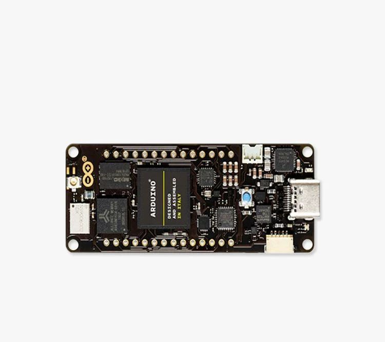
Original Arduino MKR WAN 1300 ABX00017 Dipole Antenna GSM X000016
Product introduction
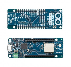
The Arduino MKR WAN 1300 is designed to provide a practical and cost-effective solution for manufacturers seeking to add LoRaR connectivity to their projects with minimal networking experience. It is based on the Atmel SAMD21 and Murata CMWX1ZZABZLo-Ra modules.
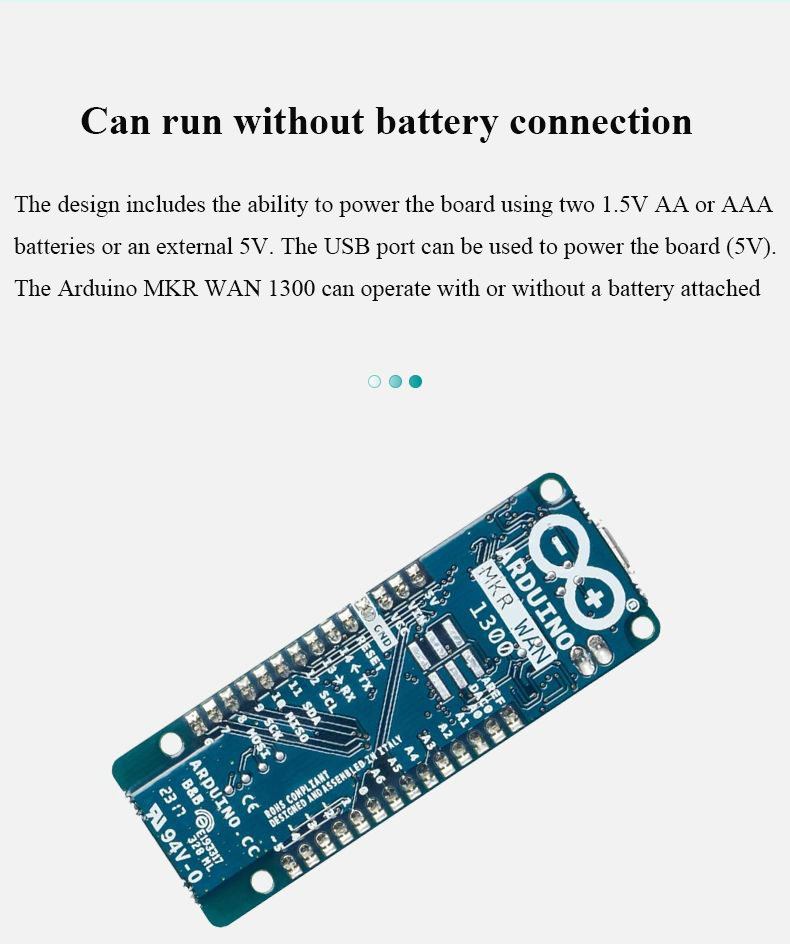
The design includes the ability to power the board using two 1.5V AA or AAA batteries or an external 5V. Switching from one source to another is done automatically. Good 32-bit computing power similar to the MKR ZERO board, a usually rich set of I/O interfaces, low-power LoRa 8 communication, and ease of use of Arduino software (IDE) for code development and programming. All of these features make the board suitable for emerging iot battery-powered projects in a small form factor. The USB port can be used to power the board (5V). The Arduino MKRWAN 1300 can operate with or without a battery attached and with limited power consumption.
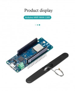
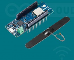
The MKR WAN 1300 must be used with a GSM antenna that can be attached to the board via a miniature UFL connector. Please check that it can accept frequencies in the LoRa range (433/868/915 MHz).
Please note: For good results, do not attach the antenna to a metal surface such as the chassis of the car
Battery capacity: The connected battery must have a nominal voltage of 1.5V
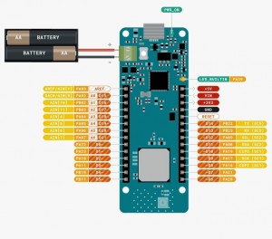
Battery Connector: If you want to connect the battery pack (2xAA or AAA) to the MKRWAN 1300, use screw terminals.
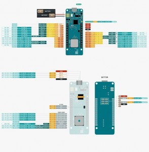
Polarity: As indicated by the silk on the bottom of the board, the positive pin is closest to the USB connector
Vin: This pin can be used to power the board via a regulated 5V power supply. If power is supplied through this pin, the USB power supply is disconnected. This is the only way you can feed 5v (range 5V to maximum 6V) to the board without using USB. The pin is an input.
5V: When powered from a USB connector or the VIN pin of the board, this pin outputs 5V from the board. It is unregulated and the voltage is taken directly from the input.
VCC: This pin outputs 3.3V via the onboard regulator. This voltage is 3.3V when using USB or VIN, which is equal to the series of two batteries when using
LED lights up: This LED is connected to a 5V input from USB or VIN. It is not connected to battery power. This means that it lights up when the power is coming from USB or VIN, but stays off when the board is using battery power. This maximizes the use of energy stored in the battery. Therefore, in the case that the LED ON is not bright, it is normal to let the circuit board rely on the battery power supply to operate normally.
|
Product parameter |
|
|
A powerful board |
|
| Microcontroller | SAMD21 Cortex-M0+ 32-bit low power ARM⑧MCU |
| Radio module | CMWX1ZZABZ |
| Circuit Board Power Supply (USB/VIN) | 5V |
| Supported batteries (*) | 2xAA or AAA |
| Circuit operating voltage | 3.3V |
| Digital I/O pin | 8 |
| PWM pin | 12 (0,1,2,3,4,5,6,7,8,10,A3-or18-,A4-or19) |
| UART | 1 |
| SPI | 1 |
| I2C | 1 |
| Simulate the input pin | 7(ADC8/10/12 bit) |
| Analog output pin | 1个(DAC10 bit) |
| External interrupt | 8(0, 1,4,5,6, 7,8, A1-or16-, A2-or17) |
| Dc current for each I/O pin | 7 mA |
| Flash memory | 256 KB |
| SRAM | 32 KB |
| EEPROM | No |
| Clock speed | 32.768 kHz (RTC), 48 MHz |
| LED_ BUILTIN | 6 |
| Full speed USB devices and embedded hosts | |
| Antenna power | 2dB |
| Carrier frequency | 433/868/915 MHZ |
| Work area | Eu/USA |
| Length | 67.64mm |
| Breadth | 25mm |
| Weight | 32g |
Products categories
-

Phone
-

E-mail
-

Whatsapp
-

Skype
-

Skype
-

Skype


