


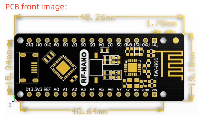
RF-Nano compatible with ATMEGA328P Nano V3.0 Integrated NRF24L01 wireless CH340 serial port module
Product Introduction:
The NF24L 01+ chip is integrated on the board of the RF-NANO, making it have unlimited transceiver function, which is equivalent to combining an ordinary Nano board and an NRF24L01 module into one, which is more convenient to use and small in size. The RF NANO has exactly the same pins as the common Nano board, making it easy to transplant.
Product parameters:
Processor description:
Arduino RF-NANO microprocessor is ATmega328(Nano3.0), with USB-Micro interface, at the same time has 14 digital input/output 0 (of which 6 can be used as PWM output), 8 analog input, a 16 MHZ crystal oscillator, A USB-Micro port, an ICSP header, and a reset button.
Processor: ATmega328
Operating voltage: 5V Input voltage (recommended) : 7-12V Input voltage (range) : 6-20V
Digital I0 pin: 14 (of which 6 as PWM output) (D0~D13)
Analog input pins: 6 (A0~A5)
I/O pin DC current: 40mA
Flash Memory: 32KB (2KB for the bootloader)
SRAM: 2KB
EEPROM: 1KB (ATmega328)
USB converter CJ chip: CH340
Working clock: 16 MHZ
Power Supply:
Arduino RF-Nano Power supply: Micro-USB is connected to C] power supply and external vin is connected to 7 ~ 12V external DC power supply
Memory:
The ATmega328 includes 32KB of on-chip Flash, 2KB for Boot-loader, 2KB of SRAM, and 1KB of EEPROM.
Input and output:
14 digital input and output: the working voltage is 5V, and the output and access limit current of each channel is 40mA. Each channel is configured with 20-50K
Ohm internal pull-up resistor (not connected by default). In addition, some pins have specific functions.
Serial signal RX (No. 0), TX (No. 1) : provides TTL voltage level of the serial port received signal, connected to the FT232RI corresponding pin.
External interrupts (Nos. 2 and 3) : Trigger the interrupt pin, which can be set to rise edge, fall edge, or both.
Pulse width modulation PWM (3, 5, 6, 9, 10, 11) : provides 6 8-bit PWM outputs.
SPI (10(SS), 11(MOSI), 12(MISO), 13(SCK)) : SPI communication interface.
LED (No. 13) : Arduino special) is used to test the retention interface of l_ED. The LED is lit when the output is high, and the LED is extinguished when the output is low.
6 analog inputs A0 to A5: Each – channel has a resolution of 10 bits (that is, the input has 1024 different values), the default input signal range is 0 to 5V, and the input upper limit can be adjusted by AREF. In addition, some pins have specific functions.
TWI interface (SDA A4 and SCL A5) : Supports communication interface (compatible with I2C bus).
AREF: The reference voltage of the analog input signal.
Communication interface:
Serial port: The built-in UART of the ATmega328 can communicate with external serial ports through digital ports 0 (RX) and 1 (TX).
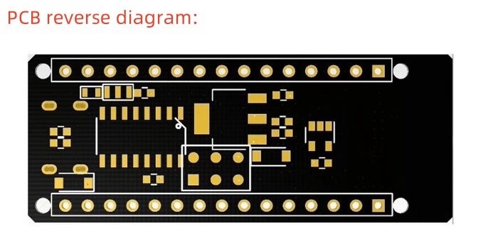
Products categories
-
Four-port mini non-managed Ethernet switch core...
-
High precision board, used for medical instruments
-

2S10AF4 flying tower 2S 4-in-1 electric F411 mi...
-

F722 40A AIO dual USB flight control electric c...
-

45AF7 V2 fly tower 2-6S FPV racing traverser fl...
-
Android board all -in -one motherboard self -se...
-

Phone
-

E-mail
-

Whatsapp
-

Skype
-

Skype
-

Skype